Instructions, tips and tricks

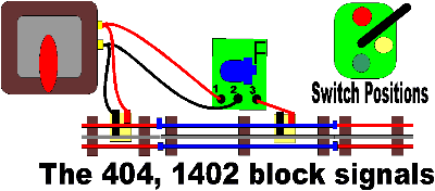
Some of Marx's earlier signals got the process in reverse. The #404 and #1402 were like that. Instead of isolating the common rail (center), this one isolated the outside rails. This block signal will control the isolated area.
There is a manual switch on top which has three positions. Red cuts power to the blocked section, stopping trains. Green restores power. Yellow is just for show. It does not power the track. The original instructions advised leaving out track pins on the outer rails to be blocked off. That does not always work. Use fiber or plastic insulating pins instead.
The wiring is depicted here with regular lockons.

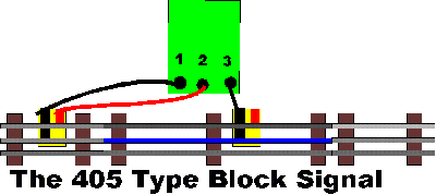
The #405 type block signals are a type that requires blocking off the center rail instead. These are notable by having the manual switch on the stand rather than the top. A smaller switch regulates speed. On the #405, Yellow means reduced speed, which you can set via the signal. It is depicted here using regular lockons.
*********

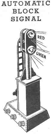
The #454 type block signals (illustrated below) are among the most complex Marx accessories. They only have red and green, and will work automatically. Though the illustration and original directions advise omitting track pins to isolate the center rail, it is better to use fibre or plastic pins. They assure that he rail is indeed isolated. Wires 1 and 2 might do better routed to the accessory terminals of the transformer than rely on track power.
 |
Original Instructions for the No. 454 Marx Automatic Block Signal
1) Refer to the diagram.
2) Place signal beside track facing direction of traffic.
3) The special section of straight track, and special section of curved track, with pins removed, included with this set are to be placed in your track layout, with one or two pieces of track connected between them. It will be necessary to remove one regular section of straight track and one regular section of curved track to make room for these sections. It forms an insulated length of track which is called the control zone. The length of this zone can be varied, depending on the number of track sections which are placed between then two special sections but for best results it is recommended that the control zone does not exceed four sections.
4) The track connection terminal stamped with a "3" and the single connector clip, is to be connected inside the control zone, by inserting the upright blade into the groove on the under side of the center rail.
5) The track connection terminal stamped "1" and "2", with two clips on the plate, is to be connected to the track in the same manner, but must be connected outside the control zone.
6) The transformer must be connected to the track outside of the control zone.
7) Connect the wires from the track terminals to the corresponding terminals "1". "2" and "3" on the Block Signal Base, as indicated in the diagram.
8) After the transformer is turned "on", the red or green light may be turned on by moving the control level at the back of the Block Signal to the proper position.
9) When the Block Signal light is turned to green, the control zone receives current thru the number "3" terminal and the train will proceed past the Block Signal.
When the Block Signal lights are turned to red, the control zone will not receive current, and the train will stop when it reaches the insulated section of track called the control zone.
10) After the train has been stopped by the red signal it can again be placed in motion by turning the Block Signal light to green.
Click here to return to Marx Accessory Index