Instructions, tips and tricks
Marx switches are unique, in that they were made to accommodate the long copper pickup shoe and thick, geared "fat wheel" of the pre-1950 Marx trains. Trains with the fat wheel cannot negotiate Lionel switches. The early metal-based Marx switches had gaps that would catch the pickup roller of Lionel trains. Later plastic-base switches had a feature which allowed passage of both Lionel and Marx trains, even those with fat wheels.
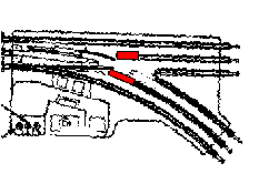
There is a trick to prevent Marx switches from snagging a round pickup roller. Track pins are inserted (as shown in red below). The must be inserted far enough to allow free operation of the switch, but not so far as to leave a wide gap.

Track power makes the train run, but Marx switches' mechanism runs on transformer power. Hence there are three terminals beside each pair of buttons, and a pair of terminals on top of the controller. The transformer's accessory terminals are hooked directly to the pair of terminals. That's why you cannot use a Lionel or K-line controller on Marx switches. (Should you need a controller, the Atlas switch controller used for two-rail trains [HO, N, O] works perfectly) Marx's controller powers a pair of switches. Atlas controllers allow you to connect each switch individually.
It is simple: hook the two wires from the pair of terminals to the transformer. Hook the switch wires from the controller to the switch. On both controller and switch you will see clearly marked the words RED, GREEN and BLACK beside the appropriate terminals. Older switches also had a dot of the color painted beside the terminal. Most just have the words themselves painted or molded.


The original instructions from the #1590 are reproduced below.
Original Instructions
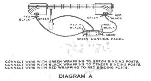
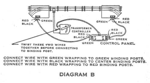
1) Connect switches to the control panel by means of the three wire cables. Each wire of the cable identified by a colored cotton wrapping which appears at the end of the wires [or use colored wire]. Connect the Green wire to the binding post with the green base, the black wire to the center binding post, and the red wire to the binding post with the red base. (See Diagrams A and B)
2) Connect the opposite ends of the three wire cables to the control panel. In the same manner, with the red wire opposite the red button, the black wire on the center terminal and the green wire opposite the green button as indicated by the markings on the control panel. (See Diagrams A and B )
3) To connect the control panel with the transformer-controllers (with three binding posts) connect the two wire cable opposite the markings "To Transformer" on control panel and the opposite end on the two binding posts on the transformer, twisting the wires together with the wires on the track connector terminal, before fastening to the binding post. (See Diagram A and B)
5) To connect control panel with the transformer which has four binding posts, wires should be connected to the posts marked "Accessories."
6) The position of the switch is changed by pressing down on the red or green button on the control panel. By pressing down on the green button, the position of the switch is set for straight line traffic, and by pressing down on the red button, the position of the switch is changed to allow the train to travel on the curved portion of the switch. Handle carefully to avoid any damage which might result from a fall or other rough handling.
Click here to return to Marx Accessory Index