Instructions, tips and tricks
Louis Marx had his own response to Lionel's Bascule Bridge. In typical Marx fashion, it was humble in comparison. Lionel's bridge was electrically-operated via a remote controller, and it was very long. Marx's bridge was smaller. The Marx Lift Bridge was powered by a hand crank!
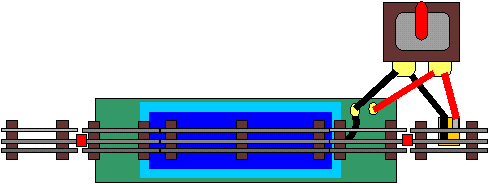
The technology behind the Lift Bridge is that of the isolated block. The center rail (or "common ground") is isolated off with fiber pins / insulated pins as shown in RED on our illustration. This creates a block. When the lift bridge is open, any train entering the block will be stopped. Concurrent with the bridge's lifting, electrical contact to the center rail is cut.
Naturally, you can extend the block to either side by placing the insulating fibre pins further from the bridge itself. One extra track section should be enough for a reasonably long block.
NOTE: IT IS IMPORTANT TO WIRE THE BRIDGE TO THE TRACK TERMINALS, NOT THE ACCESSORY TERMINALS!
Electrically, this device is a track accessory. It is not track-side, and so must use track power. The terminal closest to the outside of the bridge is wired to the terminal that powers the outside rail. The inside bridge terminal, located closest to the bridge itself, is wired to the inside rail. The inside terminal must be wired to the transformer terminal powering the inside rail on the layout.

Original Instructions
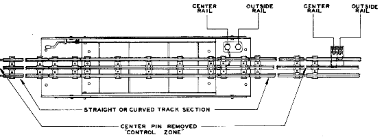
1) This bridge, in length, is equivalent to two sections of Marx #601 Elec. Straight Track. Place the Bridge in your track layout by forming a "control zone" by removing the center rail track pins from the extreme ends of the adjoining sections of track at each end of the Bridge (see diagram).
2) Make connections form terminal points at end of Bridge to track connection terminals on your transformer. It is important that your connection from the binding post which governs the center rail of the Bridge be made to the same binding post on the transformer that you have previously used to make the connection from the transformer to the center rail of your regular track connector located outside the control zone. The inside binding post located on the Bridge governs the center rail and can be further identified by the wire which runs from this binding post to the connecting plate under the center rail at the end of the Bridge.
If the connection is not made in this manner, you will have a direct short on your transformer and your train will not operate.
Therefore, in after making these connections, your train does not operate, immediately shut off your transformer, to avoid burning out, and recheck your connections to be sure that the same binding post on the transformer governs the center rail on the Bridge, as well as the center rail on the track connector located outside the control zone.
3) Connections from the Bridge to the transformer as mentioned in Paragraph 2 above should never be made to the accessory binding posts of a transformer, but must always be made to the TRACK binding posts of the transformer as instructed.
4) With the bridge properly installed, when the Draw Bridge is lifted by means of the crank located at the end of the Bridge, your locomotive will stop as soon as it reaches the control zone located between the points where the center rail pins have been removed. When the Bridge is lowered, the control zone is energized and your train will proceed to run. In raising or lowering the Bridge do not force the crank by turning after the Bridge has reached the maximum height or has been returned to contact with the center rail.
5) If desired, the Bridge can be permanently fastened into your track layout by means of the holed pierced in the stationary end sections of the Bridge.
6) If desired, for certain layouts, after the stationary sections have been permanently installed, the side rails can be removed from your Bridge layout by removing the screws located at each end of the rails.

Click here to return to Marx Accessory Index