(This section is reprinted from a manual whose copyright expires years ago. It has been re-edited, updated and corrected for today's model railrans. Though written for O / O27, the information can be adapted to HO and N scale)
One of the most fascinating things about owning a miniature train is the planning and building of a model layout that has all the features of an actual railroad system. With today's wide selection of tracks and accessories it is easy to duplicate any of the operations of the big roads. Like all hobbies model railroading develops slowly. You can start with a layout that fits your income, and add to it year by year.
First step is to get out your pencil and put down a few ideas that will guide you in your planning. How much space is available for your complete layout? It is better to overestimate your space requirements than to find yourself later in cramped quarters, that will necessitate ripping up track and starting over. Next, how much rolling stock do you have, and how much more do you plan having?
When you plan your first track layout, be sure to allow for future growth of your rail system. As you add to your rolling stock you will want more sidings, classification yards, wyes, reverse loops. The siding in today's layout may tomorrow become a complete new branch of your railroad empire.
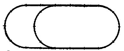
Here you will see a few of the simpler types of starting layouts. These are "0" track. "027" layouts will be slightly smaller.

Figure 1. - Overall dimensions: 82" x 32", Track requirements: 8 sections straight, 10 sections curved, pair of switches
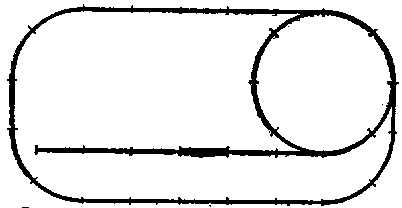
Figure 2.--Overall dimensions: 82" x 41". Track requirements: 14 sections straight, 9 curved, 3 switches, 1remote control section.
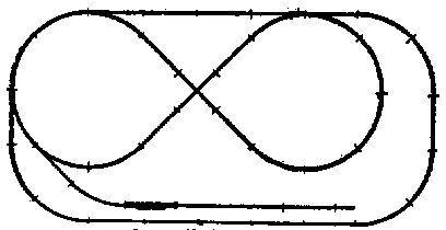
Figure 3.--Overall dimensions: 82" x 41" Track requirements: 15 sections straight 14 sections curved, 5 switches, one 90 degree crossover, one remote control section.
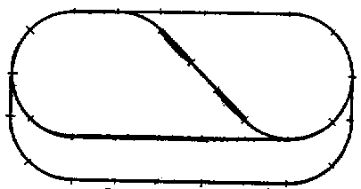
Figure 4.--Overall dimensions: 82" x 41", Track requirements: 14 sections straight, 10 sections curved, 4 switches, 2 remote control sections.
These Are Some Simple Switch Configurations Used on Model Railroad Track Layouts:

The ideal location for a permanent layout is on a. large table or specially built "run-around" wall shelving. Floor layouts risk the perils of stepped-on track, they are awkward to get at and must be broken up when the floor needs cleaning.
Favorite spots for waist-level train setups are dry cellars, attics, spare rooms and garages. The diagrams below illustrate simple methods of building wall shelving or tables. Platforms can be cheaply constructed of old lumber or second-hand plywood. Plywood has definite advantages in that it requires little cutting or fitting and simplifies drilling of holes for hidden wiring. If you construct a table arrangement be sure that the legs are well cross-braced. Wall shelving, too, should be sturdily built to prevent sway and unsteadiness.
One of the principal reasons for the shelf or table layout is to bring model train operation to a realistic view angle. Although there is some dispute as to the correct height from the floor, the general agreement is that 40 inches is about right for adults, a height of about 26 inches for the seven or eight year-old. For a father-and-son layout it is possible to construct a narrow six-inch step to take care of the junior partner.
You will undoubtedly want to have some mountainous sections on your layout to make use of the grade-pulling power of your locomotive's "rubber tires" or "Magne-Traction". Be sure that your high-leveI roadbeds and overpasses are securely anchored to the platform so that train vibration will not loosen them, One caution: do not start track grades too sharply or the pilot of your locomotive may strike the third rail in passing, causing a "short."
Here are five intriguing layouts that you can shoot for when you start planning your railway system. The setups in Figures 66 and 67 are good examples of how you can begin with simple loops and gradually expand with the addition of switches and sidings. Any one of these layouts, when finished, can handle several trains, and all are planned for both passenger and freight service.
All accessories shown are available at a well-stocked train dealer, with the exception of the turntable in Figure 69. You can build this turntable yourself from plans furnished by model builder magazines, You will, of course, want to add a number of accessories such as semaphores, block signals, etc.
These drawings give you an idea of the number of track sections, switches, and remote control sections needed. You will note that some layouts call for the use of half-track or odd lengths. Your train dealer can supply you with "0" or "O27" half-track. To make odd lengths, track can easily be cut by placing it in a vise and using a hack saw.
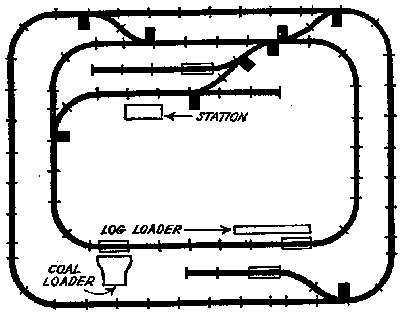
Figure 66
The layout shown in Figure 66 is an excellent road to fit on a large table or an around-the-room layout. It permits simple operations, even though two trains may be run in opposite directions. Space needed: 130" by 110"
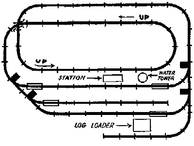
Figure 67
The layout illustrated in Figure 67, requires only four switches, Crossing at lower left-hand corner can be accomplished by grading with overpass, giving good opportunity for "Magne-Traction" and rubber-tired trains..Space needed: 130" by 100"
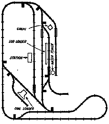
Figure 68
In Figure 68, you can start with the entire big loop around the table. Later, you can insert additional sidings, such as the station siding, and the house track where the log-loader is located. The coal loader siding can be added when convenient, and can be placed almost anywhere on the road. Final addition could be the reversing loop on the bottom. Space needed: 140" by 160"
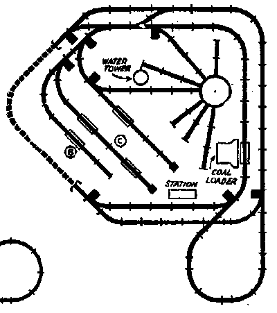
Figure 69
Figure 69 presents the most interesting possibilities for freight handling and future expansion. The three sidings in the center can be graded for "hump" classification yards. The track shown dotted at the left indicates that it is beneath a mountain. Space needed: 140" by 120'.
These drawings, except Fig. 67, do not indicate any grading of track beds. This feature has been omitted because grading will be greatly influenced by the location of your layout. However, as mentioned before, you will definitely want to have varying levels of roadbeds to make full use of the climbing power of your locomotive.
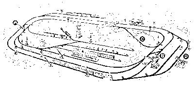
Figure 70
Figure 70 is a double track main line with a crossover A and B on either end and a reversing loop C, Complete yards are in the center and industrial sidings are at point D.
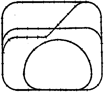
Figure 71
Figure 71 shows what can be done by using both "0" and "072" track. You can start with a simple rectangle of "0" track. Inner rectangle with crossover and "072"' oval can be added later. Space: 96" x 85"
The return of "072" wide-radius curved track sections is a boon to model railroaders throughout the country. An almost unlimited variety of layouts can be accomplished through the mixture of."O" track and "072" curved sections. "0" and "072" track have the same gauge, i.e., distance between running rails, but an "072" circle measures nearly 74 inches across, while an 'O" track circle is only 31 inches.
The wide-radius curves afforded by the use of "072" track add a great deal of realism to model operation by allowing trains to round curves more gracefully at high speeds: It is definitely preferable on curves where a grade is involved. Just as in real-life railroads, the long, slow curve at the bottom of an incline permits the locomotive to pick up traction much more easily.
The "O" track curved section still plays a vital part in the model layout. Its use prevents the layout from spreading out too much. It is usually a better choice for sidings and yards.
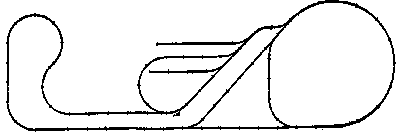
Figure 72
Figure 72 shows an interesting combination of the two types of curved track. Layout has two places for reversing the direction of the trains, one in the wye at lower right and the other in the "run-around" in the sidings in the center. Two end loops can later be joined at the top by a long run of straight track. Space: 221" by 74"
"Scenery brings it to life." Yes, landscaping is one of the most important parts of building a model pike. General planning of it should take place at the same time you're figuring out your railway system, and some of the actual work must be done before you lay a single section of track. Mountainous areas, rivers, valleys should be in place before track laying is done, so that working on them will not disturb your roadbed. Location of towns will depend on placing of your industrial siding and passenger stations. Keep in mind that you are developing an entire community and countryside. Everything you place in it should have a reason for being where it is.
The basic terrain (hills, valleys, etc.) can be made of wire mesh, molded over wooden supports and covered with papier-mache or plaster. Coloring is entirely up to you and will vary depending on the particular part of the country you want to represent.
Buildings such as houses, factories, churches can be constructed from plans furnished by model magazines, or from kits available at hobby shops. Once you've got the knack of it you can make all kinds of unusual buildings from your own designs.
Most of the landscaping can be done with odds and ends you'll find around the house. Actual stones will provide boulders for your mountainsides, fine sand will make roadways. Dried coffee grounds make cultivated fields, and dirt patches. Trees can be made from wire and steel wool, or pieces of sponge, Some model fans prefer Norwegian Lichen for greenery.
There is one general rule to follow in landscaping your layout - don't hurry. Take plenty of time to make each detail as life-like as possible. You'll find that working on it is as much fun as Iooking at the completed job. When you're finished, you'll have something to really be proud of.
No matter how little you know about basic electrical principles when you start, you will find yourself becoming more and more familiar with them as your model pike progresses. You will discover that there is no end to the unusual effects you can produce. Some model fans have gone as far as to create thunder storms and the flashing of northern lights in the backgrounds of their layouts.
For instance, you can add a lot of excitement to your train operation through wiring effects such as these two.
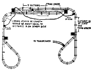
Figure 75
Figure 75 shows a wiring diagram of an automatic railroad on which two opposing trains can run indefinitely, never colliding. The secret, of course, is in letting the trains control each other. On this automatic system, a train emerging from the siding activates the train that has been deadened on the other siding. At the same time it throws switches in the proper manner.
In the operation illustrated below in Figure 76, ground rails on the sidings are insulated so that a train always halts on them. A train at point A will provide a ground circuit through an insulated section and start the train at point B. Train A goes into the' siding C, and stops. Train B goes on to complete the circuit at point A and start train A again. B takes the siding until A completes the cycle and the whole procedure continues indefinitely.
The switches are wired so that when one is open, its opposite number automatically closes.
The method is simple enough and requires little work. Special insulated "O" track sections as well as fibre pins are available through your train dealer.
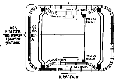
Figure 76
Most intricate of all model railway systems---and the most excit'ing of all -is the one that requires the services of a number of operators. Such systems are just the thing for model railroad clubs or for families in which several members all want to participate.
The one shown here is set up for four operators.

The No. 1 man is engineer of the outside loop train, controlling the train only, No. 2 man is dispatcher and operator of the outside loop, controlling switches, signals and any operating accessories. All semaphores, block signals are remote-controlled by dispatcher, so signal tells him to reduce speed to take switch and pass into siding A. Yellow light on 153B (replacing red light on signal) indicates reduced speed to take crossover B.
When crossover switches at B are set to take trains from outside loop, switch C is also automatically set to take tra;in in on track D. This arrangement reverses train so that it runs in the proper direction on inside loop.
Engineer No. 3 must also follow directions of signals controlled by operator 4. When, he is to pass out onto`the outside loop, he first backs into track D, then through E, thus reversing direction. Then the engineer must watch them carefully in the operation of his train.
The inside loop also has both train engineer and dispatcheryardmaster. No. 3 man runs the inside loop train, while No. 4 controls track operations and accessories.
Now comes the interesting part! Switches and cross-overs permit No. 1 train to move into No. 4's railroad and train No. 3 into No. 2's layout. All operators must be on their toes for such transfers.
Operating this railroad is like this: Engineer No. 1 must watch 151 semaphore for warning of open bridge. A yellow light on 153A is ready to take crossover F to outside loop.
No. 2 operator controls lift bridge, water tower, lumber loader, switches and all remote control track sections on outside loop.
No. 4 operator controls coal loader, coal ramp, all switches and remote control track sections on inside loop.
This type of multiple-operator railway system is the closest approximation of real railroading there is, and, limited only by available space, it can be expanded to include six, eight and ten operators. It's a sample of the thrills in store for model railroaders,
Click here to return to Main Page