Model railroad signals and trackside accessories are usually operated automatically by means of "contactors" actuated by a passing train. Some of the contactors are worked mechanically by the weight of the train. Others are operated electrically by the train wheels making an electrical contact with the contactor surface.

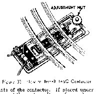
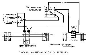
No. 145C Contactor is an "Off On" electrical switch operated by the weight of the train and is furnished with No. 151 Semaphore, No. 145 Gateman and No. 252 Crossing Gate. Place the contactor underneath the track so that one track tie rests firmly on the lever plate of the contactor. If placed under curve, the adjustment nut should be toward the center. Do not fasten down the track for several sections on either side of the contactor because the track must remain free to bend under the weight of the train. Then make the wire connections shown in the diagrams. After all connections are made and transformer power is on, adjust the contactor. With the train stopped on the track several sections away from the contactor, turn the adjustment nut either way until the signal operates, then turn the nut back just enough to return the signal to its normal non-operating position. By varying the tension of the adjustment nut the signal can be made to respond either to the weight of the heavy locomotive or to the lightest car.
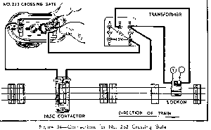
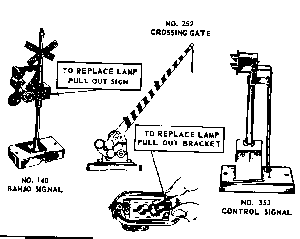
This accessory is connected to No. 145C contactor and transformer a! shown in Figure 34. The order of wires connected to contactor does not matter. Note method for removing lamp bracket from base of Crossing Gate
No. 145 GATEMAN and No. 151 SEMAPHORE
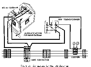
The two signals illustrated on this page are wired in a similar way. Note that three wires go to each accessory, one to the lamp, one to the operating coil and the third to the "ground" side of both the lamp and the coil. The lamp wire is connected to the right-hand or bottom contact of the 154C contactor, while the coil wire is connected to the left-hand or top contact.
To make connections to the 145 Gateman the roof of the hut must be lifted off. To get at the lamp for replacement ,the spring lamp bracket must be lifted up as shown by dotted lines.
No. 153C Contactor, furnished with 153 Block Signal, is very similar to No. 145 contactor and is installed and adjusted in the same way. Note, however, that it has three terminals instead of two so that it can control two electrical circuits, closing one while opening another. In No. 153 Block Signal, which has two separate lamps, the green light goes out and the red goes on as the train passes over the contactor.
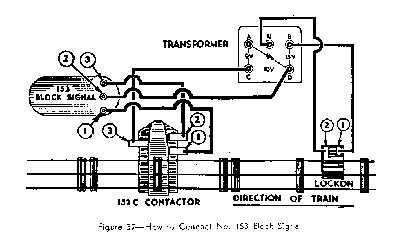
Although the diagrams on these pages show a separate contactor for each signal, two signals located in different places in the layout can be connected to the same contactor so that the passage of the train operates both of them simultaneously. Such "parallel" connection, however, is recommended only with the larger transformers.
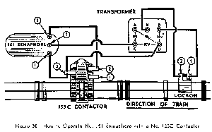
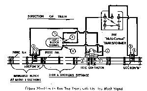
By installing an insulated track block and using a 153C contactor to control its power supply, it is possible to operate two trains on the same layout. Usually either a 153 Block Signal or a 151 Semaphore is used with this installation for the sake of realism. Be careful to make all wiring connections exactly as shown. Note particularly that a portion of track at least three sections in length is insulated from the rest of the track by means of fibre pins inserted in the center rails at the ends of the block.
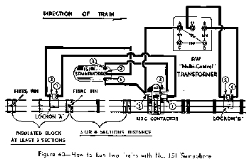
As train No. 1 crosses the contactor, it changes the position of the track signal to indicate "Stop" and at the same time cuts the power out of the insulated block. If train No. 2, running behind the first train, runs onto the insulated block at this time, it stops and waits until the first train passes the contactor. After the last car of train No. 1 is off the contactor, the track Signal changes to "Go", current flows back in the track block and the waiting train continues on its way. In this way, the second train can never overhaul the first train, but always remains a safe distance behind it.
In order to give the waiting train a fast start, the current supplied to the insulated block through the contactor and Lockon "A" should be 2 to 3 volts higher than the current supplied to the rest of the track through Lockon "B"
NOTE: When operating two trains automatically don't forget to disconnect their reversing "E-'Units". Otherwise the trains, after being stopped, will not resume forward motion but will remain standing in "Neutral",
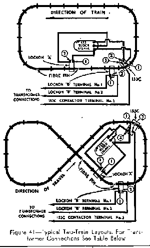
Two of the many possible layouts using 153C contactor and insulated track blocks for two-train operation are shown in Figure 41. The basic wiring of these layouts is the same as in Figure 39, If you use a 151 Semaphore instead of the 153 Block Signal follow wiring in Figure 40.
Automatic operation of trains can also be accomplished by using special insulated track. Diagrams illustrating this type of installation are found under "Build a Model; Railroad." Many other variations of these installations can be worked out.
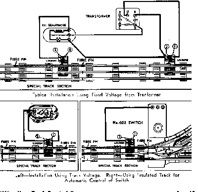
Special track sections track are used as wheel-operated electrical switches to accomplish automatic operation of accessories such as the No. 151 Semaphore, No. 252 Crossing Gate, No. 145 Gateman, and others. These sections can also be used for automatic control of track switches or to control stopping and starting of two trains running on the same track.

As illustrated above, one of the outside rails of the special section is insulated from the track ties and from the other rails. To complete the insulation of this rail from the rest of the layout, fibre pins should be inserted in both ends of the rail. Connections to the special sections are made by means of a track Lockon attached on the side of the insulated rail.
Typical use of special sections are illustrated below. When properly connected to the transformer and to the special section, the accessories will operate when the wheels and axles of a train passing over the special section complete the electrical circuit by bridging the insulated rail to the "grounded" outside rail on the opposite side.
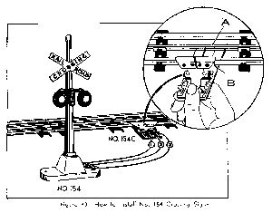
No. 154 Crossing Signal is connected directly to the track by means of the No. 154C Contactor. Attach the contactor to the track by pressing down the spring lever to raise the contact plate as shown in the inset of Figure 43; then place contactor under the track with clip "A'' gripping the flange of outside rail, snap spring clip "B" over the center rail, and release the spring lever.
As the wheels of the train roll over the contactor surface, the red warning lights of the Crossing Signal will blink alternately.
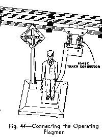
An accessory somewhat similar in operation to No. 154 Crossing Signal is No. 1045 Operating Flagman, who waves a warning flag as the train goes by a crossing.
The Flagman is connected directly to the track by means of the No. 1045C Contactor which is clamped on to any section of straight track in the same way as No, 154C Contactor. No. 1045 Flagman and its track connections are shown in Figure 44. You will notice that the inside of contact plate of both 1045C and 154C Contactors has a layer of insulating paper. This layer keeps the electrical circuit normally open. Whenever a car truck passes over the contactor the circuit is completed through the car wheels and the fIagman operates. Keep top of contactor clean.
