Lionel and others manufacture a number of realistic operating accessories which duplicate the activity of real railroad equipment. All of these accessories depend on the transformer for their operating power and work on voltages ranging from 10 to 14 volts, depending upon the accessory itself, The higher portion of this range is generally required when the motor and the working parts of the accessory are new, but the voltage can usually be decreased as the mechanism becomes worn in. In this way you will prevent unnecessary wear and prolong the life of the equipment.
While variable voltage is supplied to the track for controlling the speed of the train, the majority of operating accessories should be connected directly to the fixed voltage terminals of the transformer. Select that combination of terminals which furnishes the proper voltage for operating your accessory. When using a VW or ZW Multi-Control transformer, where the voltage for operating accessories as well as that for running trains may be set at any desired point, turn the voltage control to the lowest voltage where you get satisfactory operation.
The number of operating accessories which can be used with your model railroad is limited only by the wattage rating of your transformer as discussed in the section on Power Supply. In most cases, however, since these accessories consume power only when in actual operation, many more of them can be operated on a transformer than the total of their wattages would indicate.
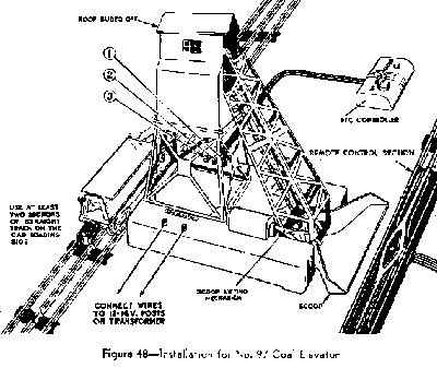
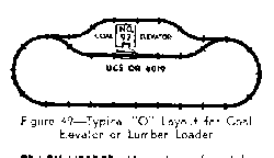
The Coal Elevator is installed between two lines of track approximately 14 inches apart with a remote control section inserted in one of the lines. See Figures 48 and 49. Lionel artificial coal can then be unloaded from dump cars into the automatic tilting scoop of the elevator where it is picked up by the bucket conveyor and carried to the storage bin on the top of the elevator. The car is then rerouted beneath the delivery chute on the other side of the elevator and there reloaded. No. 97C Controller supplied with the elevator has a button for controlling the gate of the elevator storage bin and an "On-Off" switch for controlling the motor-driven bucket conveyor. The motor of the Coal Elevator should be lubricated periodically paying particular attention to the ends of the armature shaft. However, the sprockets or any other part of the conveyor should never be lubricated or pieces of coal will stick to it and jam the conveyor mechanism

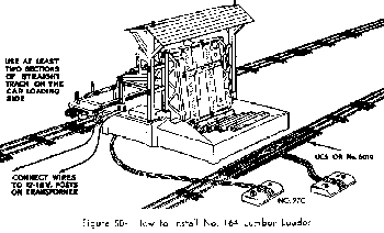
Similar in operation to No. 97 Coal Elevator is No. 164 Lumber Loader illustrated in Figure 50. The Lumber Loader is placed in a layout similar to that used for the Coal Loader. It is especially appropriate for use with remote control Lumber Cars. These cars will unload lumber into the bin on one side of the Loader. The lumber is then picked up by the conveyor chain and transported to the upper storage platform. Pressing the "Unload" button on 97C Controller will release stored lumber into waiting lumber cars. Like the Coal Elevator, the Lumber Loader should be connected to fixed voltage transformer posts furnishing 12-16 volts.
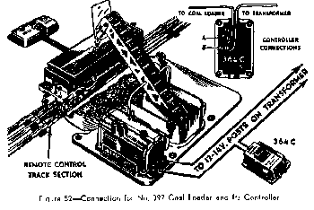
No. 364 Lumber Loader and No. 397 Coal Loader do not require any special track layout but can be located along any straight stretch of track, as shown in Figures 51 and 52. A remote control section is placed in front of the accessories in such a way that operating lumber or coal cars can be unloaded into the receiving bins. Motorized conveyor belts then carry the material from these bins and reload it into the waiting empties.
Note that in the case of the Coal Loader the coal car is loaded and unloaded from the same position on the Remote Control track, while in the case of the Lumber Loader the empty car must be moved over to the loading station in order to be reloaded. Adjust the location of the accessories until you obtain good loading and unloading action.
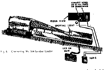
The conveyor belts in both the Lumber and the Coal Loaders are started and stopped by means of the 364C Controller, shown in Figure 52.
Coal Ramp Set consists of the elevated ramp and a special operating Hopper Car. It can be used with either "O" Or "027" layouts. The ramp is installed on the end of a siding, and is fastened to it by means of two screws furnished with the set.
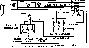
The Ramp is operated by means of a three-button controller which is wired to the ramp and to the transformer as shown in Figure 63. The three wire cable is connected to the trestle. The separate fourth wire coming out of the controller supplies power for the ramp and should be connected to a fixed voltage post of the transformer. Fixed voltage connection for the ramp will enable you to raise and lower the track voltage to maneuver the train, without interfering with the voltage supplied for the operation of the ramp.
To operate the Hopper Car couple it to the end of the train. (The train must be at least the length of the ramp.) Then back the train up onto the ramp until the Hopper Car latches to the bumper on top of the ramp. Pressing "Uncouple" button will separate the Hopper Car and the train leaving the car on top of the ramp and allowing rest of the train to depart. To dump the coal from the car to the bin underneath the ramp push the "Unload" button. To release the car from the bumper push the "Release" button.
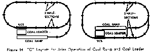
If desired, the Coal Ramp can be operated in conjunction with the No. 397 Coal Loader by mounting the bin on the loader base using two posts supplied with the Ramp.
No. 213 Lift Bridge can be used with either "O" Or "O27" track. The Bridge is approximately equal in length to two straight sections. No adjustments or special sections are required. The track is sufficiently flexible to make up for the small differences in length.
The bridge is installed simply by fitting. two regular straight track sections to both ends of the bridge so that the holes in the track ties fit over the locating tabs on the base of the bridge piers ("A" , Figure 55). The outside rails snap into clips in the base at "B". Be sure to insert three track pins into the rails at both ends of the bridge. Extra pins to fit both "0" and "027" track are furnished with the bridge.
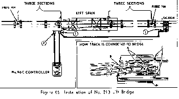
Note that three-section blocks of track at each end of the bridge are insulated from the rest of the layout by means of fibre pins inserted in the center rail. The purpose of these insulated sections is to halt the train when the bridge span is up. Wiring of the bridge is completed by running a wire between post No.1 and clip No. 1 of a track lockon placed outside of the insulated bridge approach section.
The action of the bridge is started by pressing the button of No. 96C Controller which is wired to the two binding posts on the bridge. As the bridge starts to rise power is cut out of the bridge approach sections halting the train. After the lift span reaches its highest position the action is reversed automatically and the bridge descends. After the lift span is once more in place the approach sections are energized allowing the waiting train to restart.
NOTE: When operating a layout with the Lift Bridge disconnect the locomotive reversing unit. Otherwise it will trip to neutral position as the train enters the insulated block and the train will not restart automatically.
If the bridge is actually used to span a chasm and to provide the extra clearance in raised position, the base U-channel can be removed. First fasten the bridge piers with 3 No. 4 screws on each end of the bridge. Then raise the bridge, remove 2 screws "C" and slide the U-channel out.
By installing a 153C or a 145C contactor instead of the 96C Controller, it is possible to obtain operation so that the weight of the train passing over the contactor will start the bridge motor. Pressing the controller or the contactor again, once the bridge starts coming down will stall the motor. The contactor should be placed far enough away from the insulated bridge approach so that the waiting train does not keep pressing the contactor.
No. 132 Station is equipped with automatic train control which stops and restarts the train in front of the station. The station is located anywhere along a straight stretch of track. Note that an insulated block consisting of three or four sections of track is placed directly in front of the station. Two track lockons are used in this installation, one placed inside the insulated block, and one outside and are wired to the clips on the bottom of the station as shown in Figure 56.
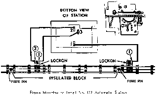
The length of time a train remains standing in front of the station is regulated by a control lever located underneath the roof of the station as shown in the inset of Figure 56. The simplest way to adjust the station is to start with the control lever at "Continuous" position and gradually move it toward "Slow" Allow the train to make several circuits in each position of the lever before moving it to a new spot.
NOTE: Don't forget to disconnect the reversing unit in the locomotive. Otherwise it will trip to neutral position when the train enters the insulated block and the locomotive will not restart automatically.
No. 30 Water Tower is wired either to a pair of fixed voltage terminals of a transformer or directly to track by means of a Lockon. (See Fig. 57).
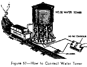
To operate the Water Tower press No. 96C Controller button. The spout will drop to "fill" the water tank in the tender. When the button is released the spout will lift. If operation of water tower is sluggish raise track voltage slightly before pushing button.
Electrical connections to this accessory are made by inserting bare ends of connecting wires into the clips on the bottom of the beacon. After electrical connections are made and power is on, lower the rotating lens housing carefully over the beacon lamp so that the pivot rests in the small cup on top of the lamp.
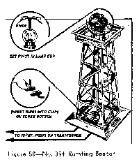
After a minute or two the lamp will heat the air inside the housing. This air streaming through the vanes on top of the housing will cause it to turn slowly. If you wish you can start it off by spinning it gently in clockwise direction. If rotation of housing stops, move the Figure 58--No. 394 Rotating Beacon pivot slightly to a. different spot in the lamp cup.
NOTE: To make sure that the beacon operates at normal speed keep it out of drafts. The housing is so light that a slight air current will interfere with the motion.
No. 465 Oil Derrick operates best on fixed voltage ranging from 10 to 15 volts. After the connections are made to two binding posts located on the bottom of the derrick, its "walking beam" pump will operate with a slow rocking motion. The timing of the pump stroke can be regulated by means of an adjusting screw.
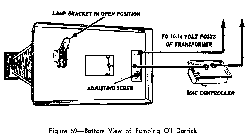
The lamp which illuminates and warms the bubbling oil column is mounted in a hinged bracket on the base of the derrick. In Figure 69 it is shown in open position, ready for removal. In operating position it is snapped shut.
Transfer Tables are used in modern engine yards and terminals to transfer diesel and electric locomotives and other rolling stock to parallel lines of track. The Transfer Table is designed to service two parallel tracks about 5 3/4 inches apart, but additional track beds can be added to extend the travel to four tracks or more.
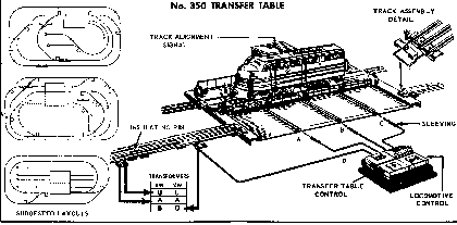
For easiest control about two track sections adjoining the table should be insulated from the rest of the layout and wired to the same voltage as the table itself. The illustration above shows one of the approaches wired in this way. A locomotive entering the insulated approach track will now stop until the transfer table rails are aligned with it exactly as shown by light in the control shack. Pushing the "locomotive" button will then energize the approach track and the table track simultaneously. The Transfer Table is provided with adjustments for all conventional O / O27 track.
The Forklift Platform is sold with a special No. 6264 Flat Car carrying a load of timbers. To unload the car the stakes on the side of the car facing the platform must be removed and the car lined up with the platform so that one side of it is centered with the guiding. slot for the forklift truck. Each time the controller button is pressed the forklift truck will move to the car, take up a timber and deliver it to the rear of the platform After unloading one side move the car over so that the other side is in unloading position.
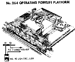
The operating range of the platform is between 10 and 14 volts and it can be connected either to variable voltage source or to any pair of transformer terminals which furnish approximately this voltage.
The Lumber Mill can be installed along any straight stretch of track. A remote control track section should be located in front of the accessory so that a lumber car can dump its load of logs onto the receiving platform at the right end of the mill. When the mill is put in operation by means of its controller, a conveyor belt carries the logs into the mill where they are apparently converted into dressed lumber which emerges at the other side of the mill.
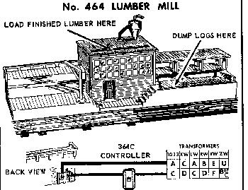
Actually the finished lumber is placed ahead of time. into the mill through a slot in its roof and the logs are removed by raising the overhead door in back of the building. The mill operates best at low voltage, Excessively high voltage may cause the lumber to jam in the mill.
The Animated Newsstand can be located anywhere on your layout. It is most effective, however, where it will enhance the action of a bustling passenger terminal. The newsstand will operate on A.C. only.
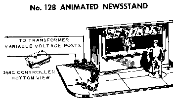
If desired, action may be automatically controlled through a 145C pressure contactor by the weight of a train arriving at and leaving a station. The 145C contactor is available from your Hobby Dealer.
Note: Do not attempt to move the figures by hand or you may disturb their driving mechanism. If this happens, the lantern will light and the mechanism will hum, but the figures will not move. To correct see your hobby dealer.
The electrical connections for the newsstand are shown above. The 364C controller is connected into one of the lines, and the lines are connected to a pair of transformer posts supplying variable voltage. Apply power and adjust the voltage for best operation, which is usually 11 to 13 volts. Excessive voltage will cause the newsstand to buzz.
The Dispatching Board is a good piece of equipment for a passenger railroad terminal, having a ticket office on one side and a huge illuminated dispatching board on the other. Its operating voltage is 10-14 volts a.c. and it is connected to a transformer through a No. 90 controller as illustrated.
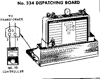
When the controller button is pressed the attendant hurries across the catwalk in front of the board and the information on the board changes automatically. The button has to be pressed for an instant only. Once the action is started it will continue automatically until the attendant returns to his post. Additional train information can be chalked in on the special "black-board" surface of the dispatching board.
Click here to return to Basic O / O27 Manuals Index
Click here to return to Main Page