(Most O and O27 switches have the same basic principles of wiring and use. However, there are differences between brands. These instructions, though helpful, may differ slightly from the particular switches you may have.)
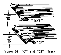
Track is made in two different sizes: "0" and the lighter "027".
The quickest way to tell the difference between them is by the shape of the track ties. (See Figure 24). Although the track "gauge" or the distance between the running rails is the same for both types of tracks--1 1/4 inches- "O" and "027" track cannot be used for the same layout without making adjustments. To be used with O, O27 must be shimmed up.

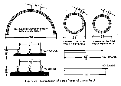
In addition to the regular length "O" track, there are half-length straight and curved section straight sections which are useful for many types of layouts. Also available are special wide radius "O42", "O54" and "072" curved tracks. The O72 sections are 14" long with 16 sections making a circle slightly more than 74 inches in diameter. All three wide-radius track sizes are made in "O" and "O27" compatible types. The three types of track are compared in Figure 25.
To aid in automatic signaling and operation of accessories there are track sections with one insulated outside rail. These must be bought separately.
O/O27 track is flexible so that it is possible to construct layouts which are not strictly symmetrical. However, be careful not to bend or distort the track too much or you will cause your train to derail. If you fasten your track to a wooden base it will be more secure and will insure better train operation. Small screws are best for this purpose, since they are easier to remove than nails. Don't screw down the track too tightly. Track should be fastened merely to prevent shifting--not to clamp it down to the base. If you attempt to screw it down tightly, you will distort the track and cause the train to operate badly.
Where special irregular lengths of track are needed cut the regular track section to proper size using fine-toothed hack saw. Smooth the cut edges with a fine file.
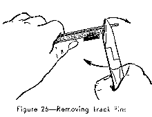
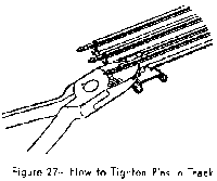
In many cases you may find it necessary to remove the steel pins from a track rail, either to place them into the opposite end of the rail or to replace them with fibre insulating pins. This can be done most easily with a pair of diagonal pliers, as shown in Figure 26. Use the rail flanges as a lever point and work the pin out gradually. Try not to distort the rail. To tighten pins in the track, or to reshape distorted or enlarged rail openings apply the pliers as shown in Figure 27. Many model railroaders make their own special track pliers by filing a round groove the size of a rail in a pair of flat nose pliers.
Besides various straight and curved track sections, many layouts also require the use of track switches and crossings. Track switches, or "turnouts" are used to connect two lines of track to enable the train to switch over to a different main line or a siding. Track switches are usually sold and used in pairs consisting of left hand and a right hand switch although single switches are available for use in constructing sidings. Manufacturers make both electric remote control and manual, or hand-operated switches. Electric switches matching "O" track are No. 022; manual "O" switches are No. 042. Electric switches for "027" track are No. 1121; manual "027" switches are No. 1024.
Track crossings enable two lines of track to cross each other like a figure 8. For "027" track there is a 90-degree crossing No, 1021. For "O" track there is a 90-degree crossing No. 020 and a 45-degree crossing No. 020X. Crossings and hand-operated switches need no special wiring of any kind. They are inserted into the layout like any ordinary track
In sections, the steel track pins make the required electrical connections. In permanent layouts it is sometimes advisable to put a small spacer or "shim" underneath a track tie adjacent to a switch, in order to keep the level of the track and the switch rails even .
Automatic switches are operated by controllers connected to the switch by 3-wire cables. Connect the center wire to the middle binding post of the switch. Connect the outside wires to the outside binding posts.
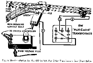
When the switch is properly installed, moving the controller lever throws the swivel rails of the switch either to permit the train to go along the straight-away, or to turn it onto the curved portion of the track. The switch and the controller are equipped with red and green lights which indicate the position of the swivel rail. When the switch is set for the train to go along the straight-away, green light shines in the controller and along the straight-away. when the switch is set for the train to go along the curved portion, red light shows in both places.
The Fixed Voltage Plug which is furnished with 022 switches makes it possible to get power for the switch directly from the transformer. Wire the plug directly to transformer following Figure 29.
The use of the Fixed Voltage Plug is optional. In small layouts it may not be necessary, for the switches will operate satisfactorily by drawing the current directly from the track. Connection is made automatically when Fixed Voltage Plug is removed.
No. 022 switches have a built-in safety device which prevents train derailment. This device automatically throws the swivel rails to the correct position to accommodate the approaching train. Notice that two rails of the switch are insulated from the track by fibre pins, as shown in Figure 28. They are part of the non-derailing feature. Do not take them out or replace them by steel pins or the switch will not operate. Remove pins only from adjoining track sections; do not disturb the switch.
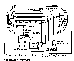
An interesting use of the non-derailing device is illustrated in Figure 30. If the outside posts of switches are connected by wires as shown in Figure 30, the train will alternate automatically between tracks "A" and "B".
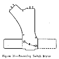
The position of the "motor" unit in 022 and 042 switches can be changed from one side to the other, if necessary for a particular layout. Remove the two mounting screws indicated by "A" in Figure 31 and detach motor unit from the switch. Insert the motor in position on the opposite side as shown by dotted line. Make sure that the driving pin is properly inserted in slot of the swivel rail and replace the mounting screws. When reversing 042 switch, change position of inside lamp wire.
No. 1121 Switches are intended for use with "027" track. The procedure for installing these switches in the layout and connecting them to their controller is the same as for No. 022 Switches, described on preceding pages. No. 1121 Switches have no provision for supplying them with fixed voltage directly from the transformer, but draw their power from the track.
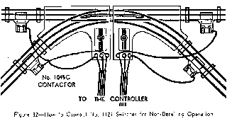
While No. 1121 Switches do not have a built-in non-derailing device, they can be made to operate automatically by a simple installation illustrated in Figure 32. Two No.1045C Contactors are required for each switch. The contactors are clamped to straight track sections adjoining the two exit branches of the switch and are then connected to the terminals on the switch box, as shown in the diagram. Note that connectors clamped to the curved branches are wired to the right-hand switch terminals: those connected to straight-aways, to the left-hand terminals.
When proper connections are made, the wheels of the locomotive approaching an "open" switch automatically make the necessary electrical connection to throw the switch to correct position in order to prevent derailment. varying the position and connection of contactors any switch in the layout can be made to operate automatically, opening and closing sidings and branch lines and routing trains according to a prearranged schedule.
Hand operated switches have no controllers or external wiring connections. They are inserted into the layout exactly as curved and straight track sections. The position of the swivel rail is changed by moving a hand lever. No. 1024 switches fit "027" track, No. 042 switches match the "O" and the "072" track.
Inexpensive and sturdy manual switches are particularly useful for infrequently used sidings, classification yards, etc., where remote control is not too important.