 To hold track sections securely
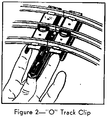
together use connecting clips supplied with the track. "O" type track clips
are pushed over the track ties. See Figure 2.
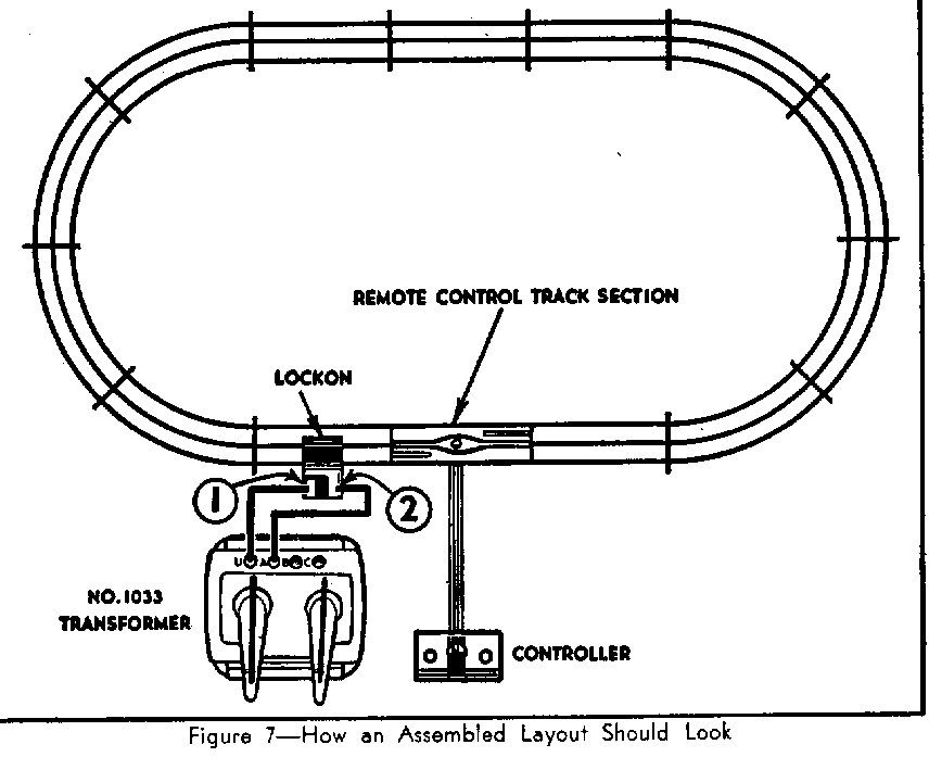
The track supplied with most outfits will make a simple oval layout as shown in Figure 7. The curved sections make up ends of the oval; the straight sections make up the sides. The special Remote Control section used for uncoupling and unloading cars goes on the side of the oval, preferably between two regular straight sections.
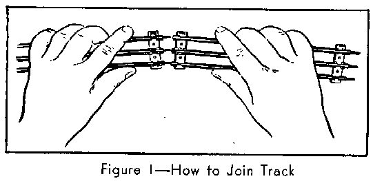
Join the track by inserting the pins of one track section as far as they will go into the rail openings of the next section. The pins should fit tightly.
 To hold track sections securely
together use connecting clips supplied with the track. "O" type track clips
are pushed over the track ties. See Figure 2.
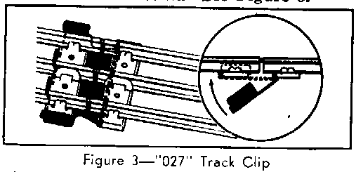
Clips for "O27" track are hooked on the tie of one section then snapped over
the end tie of the next section. See Figure
3.
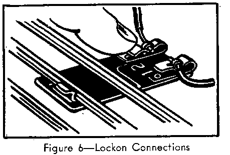
After track is assembled, attach the Lockon to a straight track section. This special clip is used for connecting rails to the transformer. Fit the flange of one of the outside rails into the wide V-shaped notch of the Lockon. Then press the Lockon upward until it snaps onto the center rail. See Figure 4.
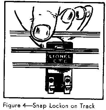
Each spring clip on the Lockon is connected to one of the transformer terminals by a piece of copper wire furnished with the outfit. The wires are coiled for convenience only and may be straightened when necessary.
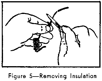
Remove insulating covering from the ends of the wires before making connections. Wrap the wire around your index finger. Rest the wire end on a solid surface. Then place a knife edge firmly on the wire and pull wire toward you. This will remove insulation without cutting the copper wire.
The other ends if the two wires connected to the Lockon go to a pair of transformer binding posts which give variable voltage. Wrap the bare wire around the screw portion of the post and screw down the thumb nut tightly. Make sure the wire doesn't slip out as you tighten nut.
